The vehicle came in with a complaint of high idling and occasional cutting out. After further quizzing of the customer, the “cutting out” turned out to be stalling when pulling to a stop. I arrived at the vehicle on an unusually cold morning after it had stood overnight. The engine started normally except for an unusually high idle speed. It’s normal to get a slightly increased idle RPM on a cold engine because the idle stepper motor gets jacked open slightly to overcome fuel inefficiencies, but this was idling just under 3000 RPM.
The RPMs eventually dropped to a normal value (hovering around 1000) as the engine warmed up. Checking the system with a scan tool found no codes logged. Before doing a road test, all the preliminary work was carried out whilst in the workshop covering mechanical defects such as a sticking throttle cable, sticking throttle butterfly, inlet plenum air leaks, etc. Each area checked out OK. For good measure the throttle body and idle stepper motor were given a good clean. Then it was time for a road test.
Once again the vehicle seemed to drive well, with good performance and no problems to report. It was tested under various driving conditions and responded well in all of them. The scan tool was also taken along to get a picture of what the ECU was seeing; as the tool can display only a few parameters at a time, a number were selected from the list and monitored in case anything stood out. The tool doesn’t keep a record of the parameters, so a passenger had to watch the display whilst the vehicle was being driven.

The only oddity was noticed while the car was stationary at lights. The throttle position sensor value shifted slightly from fully closed, although the accelerator pedal wasn’t being pressed, but how do we know that 1.2% isn’t normal? Many other systems hold the TPS open at a fixed setting and so the ECU will never see 0° or 0%. In this case the TPS was clearly capable of reading a true closed throttle position, as indicated by the 0% reading for most of the driving trip, so this, with no fault codes logged and no engine MIL, confirmed that the ECU was indeed happy with the value. The focus of the investigation turned to the TPS.
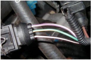 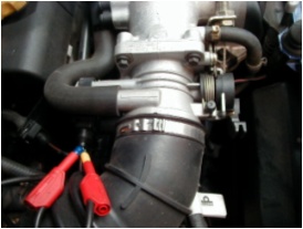
- Pin 1 Pink/Purple 5 V Supply from ECU
- Pin 2 Green/Yellow Sensor position output
- Pin 3 Pink/Black Ground
|
The sensor itself is a standard potentiometer with a slider arm in moving contact with a resistive track. Inductive sensors tend to be too expensive for an application such as this, and inductive and capacitive travel sensors are generally used for measuring small variations around a fixed point. A variable potentiometer is quite adequate here; although it hovers around the idle and light cruise positions, it still moves frequently, so fixed point contact wear is limited.
Back in the workshop the scope was hooked up to the TPS to see what exactly was happening.
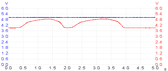
Scope channel A (blue) is measuring TPS supply voltage and channel B (red) is measuring sensor position output. The capture shows two consecutive wide open throttle (WOT) commands and displays the full scale deflection operating window. The sensor is recording the idle position as 4 V and a WOT as 4.9 V, so this was immediately a cause for concern. Why did the sensor output use only 20% of the available 5 V operating window? It didn’t make sense.
By viewing the problem with a scope you can get a much better picture. The scan tool was a big help in highlighting the problem area, but to take that problem further we needed the scope. Remember that with any scan tool you are seeing what the ECU thinks it is seeing. There is a conflict of readings here. With the scan tool registering 0% throttle angle, we could conclude that the idle position is acceptable. However, the scope shows something different: the TPS parameter of 0% is actually wrong when compared to a normally expected value of around 0.5 V. The sweep itself seems reasonable; it’s just the operating window that’s the problem.
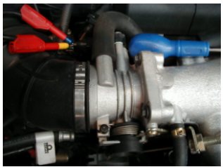
A bad sensor power supply (in this case a bad ground) would cause the sensor output signal to become generally high as seen in the capture, but scope channel A shows a good supply is present before, during, and after each WOT command. There is no power supply problem here.
This leaves the signal from the TPS as the problem, meaning that the TPS itself is at blame.
An attempt was made to further prove that the component had failed. For this, the sensor was lightly tapped with the handle of a screwdriver in the hope it would provoke the fault.
NOTE: A light tap means exactly that, not banging, knocking, hitting, or any other brute force.
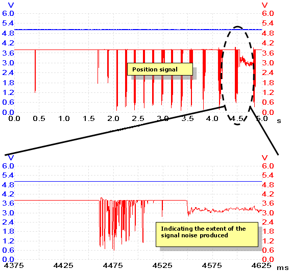
The above capture and highlighted segment was taken by the scope during repeated tapping. There’s a direct link between each signal drop and a single tap on the sensor: the signal becomes very noisy. Here are some more captures that were recorded.
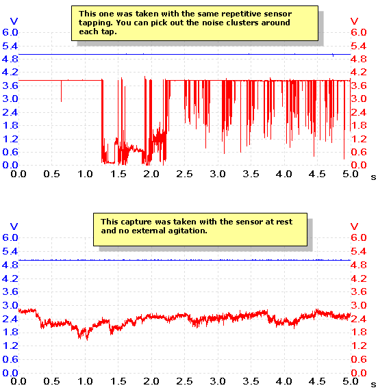
These have been included to illustrate my next finding in this investigation. During the sensor tapping and the different sensor responses, the scan tool that was still connected didn’t alter its TPS parameter. As long as the output signal stayed below 4 V (self-adapted closed throttle position), the ECU continued to register 0%; no matter how erratic the signal became. This is a classic example of how the two instruments see a fault differently.
- The scan tool sees a code on a serial cable and interprets this as a programmed unit of measure or a percentage. The value displayed is what it thinks that particular voltage represents. To see the parameter in raw voltage form, we need the scope.
- The scope shows the true signal or circuit voltage present, and in excellent detail too. The disadvantage of this is that we don’t know how the ECU is interpreting this signal; for this we need the scan tool.
So you can see the how the two instruments work neatly together. Even though the scan tool clearly wasn’t able to display the detail of the problem, it would be wrong to say that it cannot be used for troubleshooting. The scope and the scan tool make their own valuable contributions, and when combined they form an excellent troubleshooting partnership.
The investigation had been conclusive enough to get the TPS replaced.
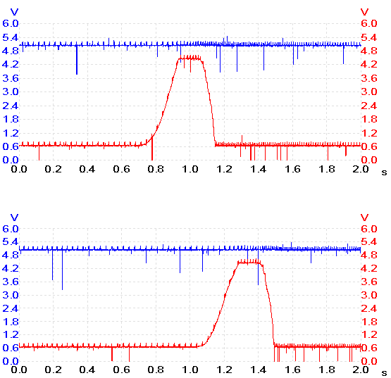
The above two captures were taken with the new sensor fitted. Don’t pay too much attention to the occasional signal spikes; these are partly due to instrumentation set to maximum sampling and partly due to signal take-off and cable routing. There are ways to tell if they are instrumentation or actual signal problems but I won’t cover that here. Note the new closed throttle voltage, with the sweep using nearly all of the supplied operating window. The vehicle was taken on road test and subjected to all kinds of driving conditions to help the ECU relearn its new TPS operation. Back in the workshop, a few throttle snap tests showed a good parameter percentage sweep.
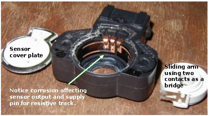
Afterwards, the old sensor was opened up to look for any signs of what might have caused the problem.

其它輔導資料 >
|

